UE5 Tutorial: Created a curved (parabolic) HUD/Widget
Hey everyone, Zach here!
In this tutorial post we will explore making a curved (or parabolic) widget effect. We will make this effect using 2D materials. This tutorial comes from a live stream I did back in 2022. Unlike the live stream I will include a method for controlling the effect on the top of the screen. In addition, the approach we are going to use, as they do not use 3D elements, will be less costly and have crisper image quality.
You will need a UI texture you want to apply this to (this can be a translucent image; in the example I am using my image is a bunch of tiny dots in a grid pattern). It does not matter what texture you use (well… it does… as you need to be able to see through the texture to see the rest of the game).
Important note:
Before we start, a quick note: This approach should not include buttons or clickable elements if you are going to be using a mouse. Why? Well, the hit boxes will not be where the mouse expects them. Take a look at these two screenshots.

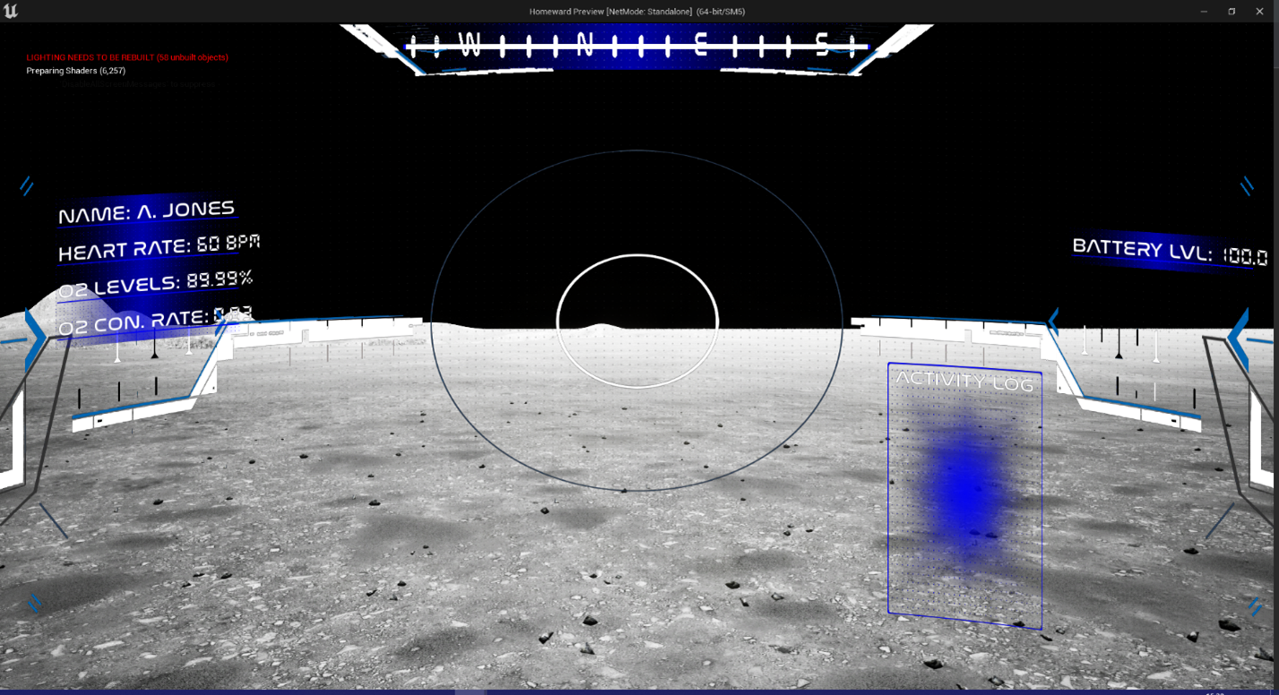
Both images are from a live stream tutorial I did back in 2022. As you can see from the top one, taken directly from the widget editor, it looks flat. That image represents where the system would see where the widget elements are. In the second image, taken from the play-in-editor (PIE), we can see the effect curve effect being applied. Notice that the elements have shifted slightly (the effect can be more significant as well).
If you want buttons on your curved widget, you will need to either 1) have the expectation that the user is using a controller or 2) use focusable buttons that respond to keyboard inputs. I will not be covering that topic in this tutorial.
A second note: Apply the material to a parent widget. The widget in the above screenshot is comprised of several other widgets. The compass, the details to the left (name, heart rate, etc.), the activity log, and the battery level are all their own widgets. The curve effect is not applied to the individual elements. The curve is applied to the “main” widget that has references to the other widgets. Do not apply the materials to all the widget elements.
Step 1: Creating a Curved Widget
This approach will curve the sides (left/right) and without control for the top and bottom.
First, create a new material. For this tutorial I named my M_CurvedEffect. (Mine is numbered cause I made a second version for this tutorial post).
Select the material result node
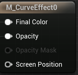
In the details panel (on the left in the default layout), change the following:
- Material Domain to User Interface
- Blend mode to Translucent

Now move to the left a far bit (we will need some space). We are going to create our curve effect. Set your nodes up as shown below:
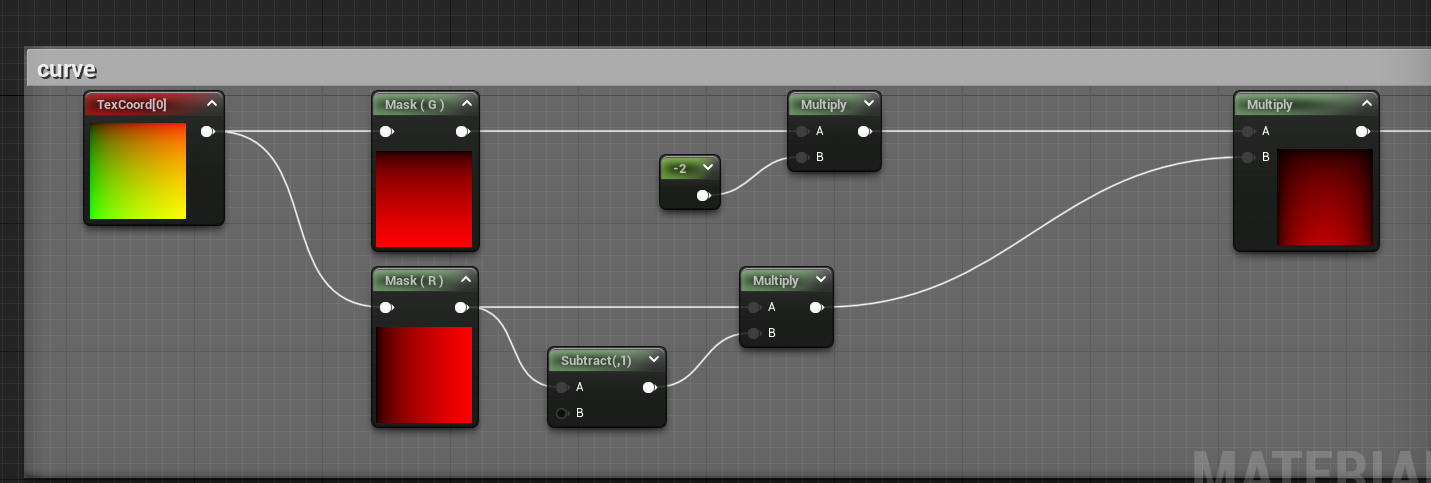
What is important to note here is that the masks are controlling the curve effect on the top (Mask (G)) and to the sides (Mask (R)). This can be seen in the actual previews of those two nodes. The effect is more pronounced in the preview on the multiply (mostly as we increase the effect with the earlier multiplies).
Also, all texture coordinate nodes use the default UV values of 1, 1.
You could (if you wanted) create parameter scalar variables for each multiple. However, I have personally (through trial and error) have found that -2 and 1 are the best choices. As for that -2, this value needs to be negative. A negative value bends the texture “away” from the camera, whereas a positive one would bring the texture “towards” the camera (experiment with that value and see).
Next, we want to apply the curve. And this is the most important part of the process. Take from the multiple you just made and set your nodes up as follows:
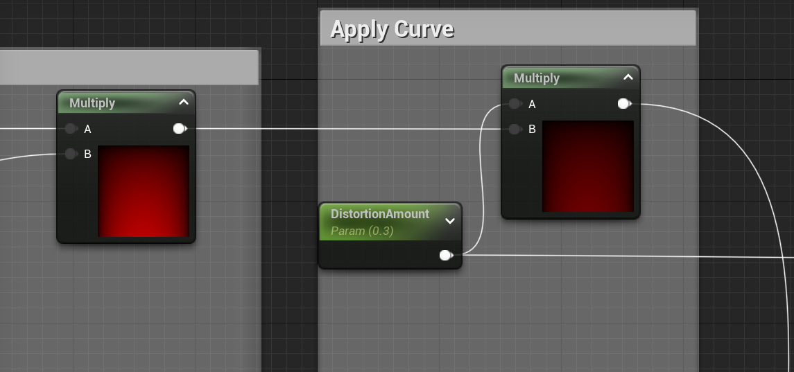
The multiply on the left is the one you already created in the previous step.
The most important aspect of this is how we apply the curve. And we control how we apply it via the “DistortionAmount” scalar variable. By making this a parameter, when we create a material instance, we can more easily adjust the value (without recompiling shaders) and we can more easily adjust it during game play (using dynamic material instance nodes).
Now comes the messy part. We need to use an if statement to blend the material so that the shader knows where to curve and how to curve. We do so by doing the following:
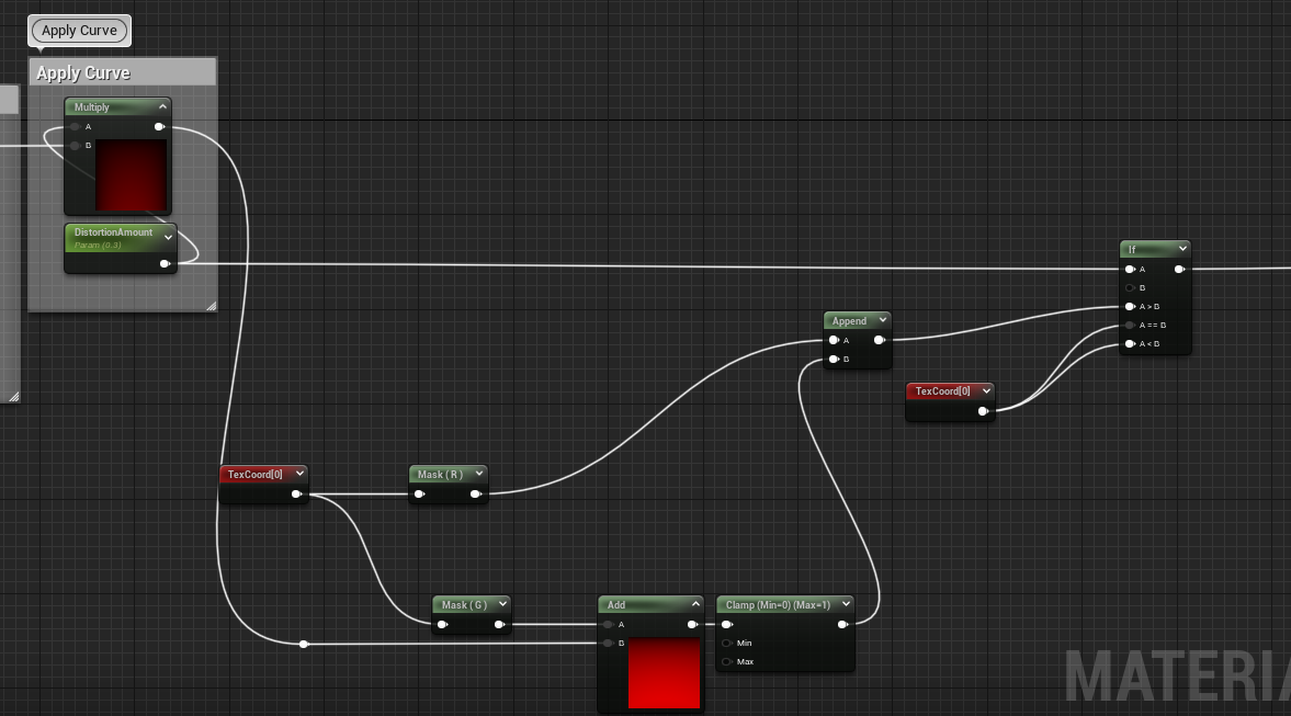
Finally, we need to apply the texture I talked about the start of this blog. Remember it needs to be somewhat translucent. The texture I am using has a grid pattern of dots to represent an old school camera effect.
Again, all texture coordinate nodes use the default UV of 1, 1.
We are going to attach the output from that if statement to a texture sample parameter 2D (I’ve named my UITexture). And then plug your texture RGB into the material result’s final color and the texture alpha channel into the material result’s opacity – as shown here:

Now there are a few options here to be aware of; first select your texture parameter.
- As this is a UI element make sure mip value mode is set to none. We do not want a UI to mip.
- Second, the sample source can either be “from texture asset” or “shared: clamp.” If you use the former, you will need to be mindful of your DistortionAmount value (from earlier). If you use the latter, the clamp means the texture will not tile outside of 0-1 range for UVs.
Finally, save and apply. You have completed the first approach.
Final result should look like this:

Before moving ahead, make sure to create a material instance of the curve material you just made. Also make a note of the texture 2D parameter name (we will need it in step 3).
Step 2: Adding control for the curve along top (optional)
So, at this stage, we have completed what I did in the live stream. But if you saw the live stream, I had a problem with lines showing up on top of my screen. I have replicated the effect below – look just above the compass:

Also note that resolution matters (we will discuss this at the end of this post).
So, let’s say you are having this issue in full screen mode. There are a few things you can do help address the issue. However, you may not be aware of the resolution of your end users and while you try your best to target the most common resolution you might miss. Or, alternatively, you want to give your end user a choice on how pronounced the effect is (after all these distortions can be jarring). So, what we can do is include one extra node and a second scalar parameter to control for the effects on the top and bottom. (Note, the bottom of the last image is also distorted, it is just harder to see).
In our curve masking (the first part we created above), we can add a control in before we multiply the two masks together. On the Mask (G) thread right after we multiple by -2 (again this is what causes the parabolic effect to move the center of the texture away from the camera), we can put in an add node with a parameter we can use to control the effect, like so:

So now the overall is: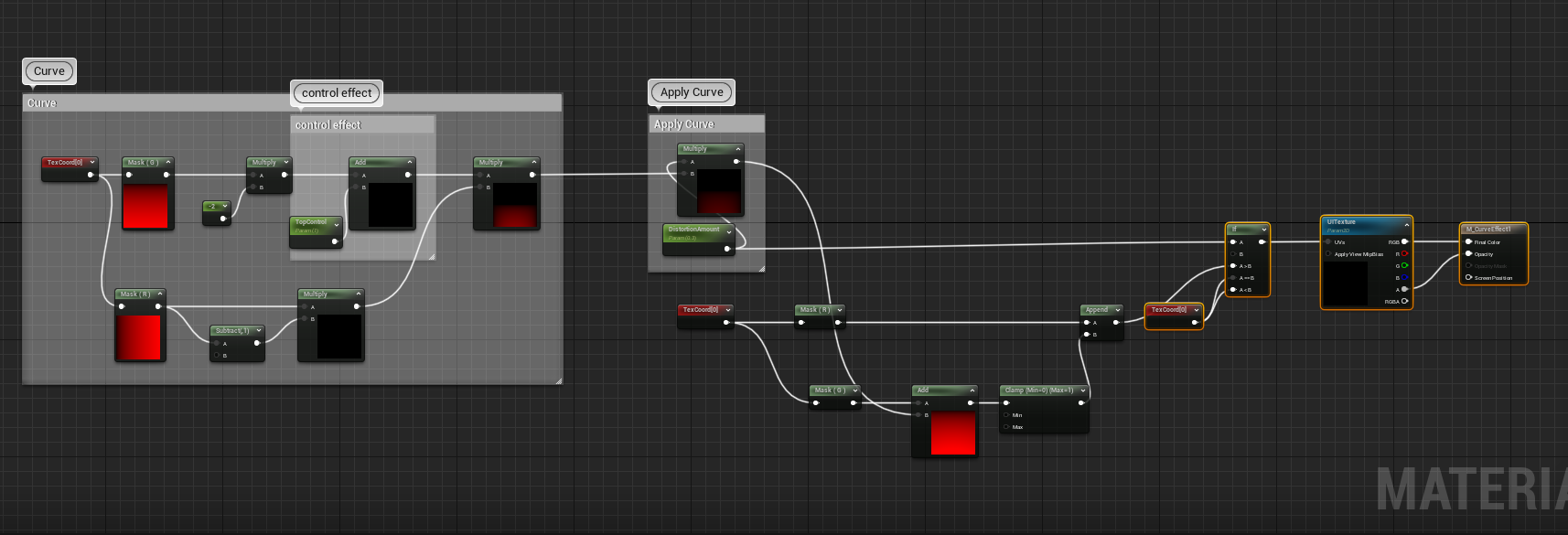
The parameter “TopControl” (I called it such as the effect with my texture is more noticeable on the top even though both the top and bottom are affected) can be changed to better control the effect. Likewise, as I mentioned earlier it may be best to experiment with that -2 (again, keep the value negative).
Now, I leave this step off because it is an extra instruction and does not add much. In fact, after initially writing this post (before it went live) I saw an AAA game that actually had the same exact issue (they also were using dots).
Right, so now that we have our material let’s apply it.
Step 2: Create a UMG widget
Create the “master” or “parent” or “main” UMG widget that will serve as the in-game HUD. (I will not cover this here). Remember a widget can have sub-widgets (like mine). In fact, in the next step I will show the exact lay out of the widget.
Make sure that your widget is using a canvas panel or some container that can contain multiple children as the “root” (we will change this in step 3).
Right, once you have your “parent” widget created move onto step 3.
Step 3: Applying the curve material
Assuming you have a canvas panel as your root (as suggested in step 2), right click the canvas panel, go to “wrap with…” and select Retainer Box. If you do not see retainer box in that menu, go to the palette and search for “retainer” and select it (it is under optimization), then right click the canvas and go to “wrap with…”. And give your retainer box a name (always name widget elements), I named mine “CurveRetainer.” The end result should look something like this:

And here you can see the Compass, Name, HeartRate, OxygenLvels, ConsumptionRate, BatteryLevel, and HelmetLog are all their own widgets. (Background, blackout, and whiteout are all images).
Next, select the retainer box, and under Effect, go to Effect Material and select the material instance version of your curve effect (or the material if you are using the base material and not an instance).
Now, one final step, still in effect, go to Texture Parameter and put the Texture 2D parameter name in from the material.

Right, and we good to go. Just make sure you creating the widget and applying to the viewport…
Additional notes:
I mentioned above that resolution plays a role in the effect. Let’s take a look at different screen resolutions to see what happens.
At 720:

At 1080:

(The way I cropped them may affect the actual image sizes).
So, there are some notable differences. For example:
The details (left hand side) do not overlap with the white gauges in the 720 version but do in the 1080 version.
- The reverse is true for the activity log on the right, where it overlaps with the white gauges in the 720 version but do not in the 1080 version.
- In the 720 version the distortion at the top of the screen is more noticeable, while in the 1080 version the distortion is more noticeable at the bottom of the screen (not so much in the screenshot though).
There are multiple ways to fix the above and I have found (using this approach in two different projects) that the fixes from one did not work in the other. So, with the examples I have been using the issue is primarily the texture has those dots.
Being frank, I cannot tell those dots are curved (I can tell that everything is curved). The solution I used for this project was to have a second widget just with the dots as an image that was not included in the parabolic effect, and I replaced the texture with the white gauges and circle texture.
In addition, I shifted the location of the other widgets to better fit 1080 (which was the lowest resolution I was targeting).
In the other project, a designer solved the problem by applying a size box. As I did not achieve that solution, I will not go into details about it. But, again, note, that after writing this post (but before publishing) while looking at an AAA title (released within the last couple of months), I noticed they had the same issue. It may be more apparent to me as I worked on my own curved UMG and thus know to look for these distortions.
Alright, that covers everything I wanted to address in this blog post. I hope to see you in the next blog post (or tutorial video). And, as always, I hope you have a wonderful day!
Recent Comments