UE5 Tutorial: Custom AI senses
Hey everyone, Zach here!
First, just a quick preview of what we are doing today:
In this tutorial post we will discuss making our custom AI senses. This blog post was inspired by a recent project piece I worked on – a clone of PacMan (I will be using classic arcade games in a new course on learning C++ in unreal). In this game, when the player eats a power pellet (in the base game there are four of these) it causes the ghost to go into “blue mode.” Otherwise known as “scaredys,” because this is when PacMan can eat them, and they flee from the character. Because I had a limited amount of time to complete the project (about 4 partial days and I had to do everything from scratch) I did not have time to create a good system for fleeing from the player. (My system did work but it could have been better). Now, we will not explore what the best system is (as it depends on so many factors and what you are trying to achieve). We will be exploring AI sense systems (in other words, my clone project inspired me to consider this topic).
So, for this blog post, we will explore using the AI system to create a custom sense that senses the player and flees from the player. I will also explain a less intensive system that does the same without using AI sense – it will be the system I used in my PacMan clone. Therefore, this blog post will be in two parts, where part 1 will cover creating an AI sense and part 2 will cover why the particular sense I created is a bad one (hey I needed to tutorial to write) and what the other options were/are (including what I used in my PacMan clone).
If you are not familiar with perception, a part of the environmental query system (EQS), in Unreal Engine then I would recommend reading this guide first.
Quick note: this tutorial was written in unreal 5.1.
Step 0: Quick setup
Open a project up, find the <project name>.Build.CS. In your public dependency add “GameplayDebugger”, otherwise you will not be able to use the debug options.
For example, in this project my public dependencies reads as:
PublicDependencyModuleNames.AddRange(new string[] { "Core", "CoreUObject", "Engine", "InputCore", "GameplayDebugger" });Step 1: Creating AI Sense and AI Sense Config classes
The AISenseConfig class will contain all the properties that are going to be used by the AI sense. This class is relatively uncomplex in that it has relatively few member methods and attributes. You can read more about it in Epic’s documentation (here).
So, let’s go ahead and create that class. As we want this class to respond to fleeing from the player, we will call it AISenseConfig_Player (not the best name, and if this were part of my PacMan game I would call it something related to packman). First, we will write click and select blueprint and then search for AISenseConfig.
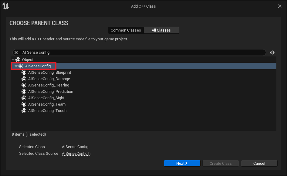
As for AISense, this class will contain the functionality/logic of our new sense. We will create this class much the same way we did the last. We will right click, select blueprint and look for AISense. This time I will name it AISense_Player. As you read this be mindful of the use of AISense versus AISenseConfig.
Step 2: Setting up AISenseConfig
Now before we get into the code, I am going to follow the naming conventions as laid out by Epic. This goes beyond their use of pascal case. This also includes the scope of declarations being made. In particular, I am following the naming and layout of AISenseConfig_Sight.h. (see my biblography at the end)
Now onto the code. We will first declare our attributes and methods in our header:
// Copyright Two Neurons, LLC (2023)

#pragma once

#include "CoreMinimal.h"
#include "Perception/AISenseConfig.h"
#include "AISense_Player.h"
#include "AISenseConfig_Player.generated.h"

/**
 *
 */
UCLASS(meta = (DisplayName = "AI Player config"))
class TN_TUTORIALS_API UAISenseConfig_Player : public UAISenseConfig
{
	GENERATED_BODY()
public:

	/* This is the class that implements the logic for this sense config. */
	UPROPERTY(EditDefaultsOnly, BlueprintReadOnly, Category = "Sense", NoClear, config)
	TSubclassOf<UAISense_Player> Implementation;

	/** Maximum sight distance to notice a target. - the radius around the AI that we use to determine if the player is near by  */
	UPROPERTY(EditDefaultsOnly, BlueprintReadOnly, Category = "Sense", config, meta = (UIMin = 0.0, ClampMin = 0.0))
	float PlayerRadius{ 10.f };

	/* This is our initializer. We will pull a few things from the parent class here */
	UAISenseConfig_Player(const FObjectInitializer& ObjectInitializer);

	/* When we implement the config this will be called up */
	virtual TSubclassOf<UAISense> GetSenseImplementation() const override;

#if WITH_GAMEPLAY_DEBUGGER
	virtual void DescribeSelfToGameplayDebugger(const UAIPerceptionComponent* PerceptionComponent, FGameplayDebuggerCategory* DebuggerCategory) const override;
#endif // WITH_GAMEPLAY_DEBUGGER
};
Let’s start with the header. The AISenseConfig is the parent class we are inheriting from and stores the methods we will be overriding. AISense_Player is the other header we created in step 1. We need our config and our sense to talk to each other. Something to be mindful is circular dependencies. I have included the sense header in the config, because that is how Epic has done it in the AISenseConfig_Sight.h.
One notable difference between Epic’s layout and my own is that I do not use ‘class FGameplayDebuggerCategory’ as they have in this header (instead I include the relevant header in the implementation file for this class). I made this choice because I was having issues accessing certain member methods of the GameplayDebugger.
As for the UCLASS specifiers, these are lifted directly from the AISenseConfig_Sight.h and renamed to “AI Player config” as we are now sensing the player.
On line 16, I am using the GENERATED_BODY() macro instead of GENERATED_UCLASS_BODY() macro, so that I can have access to the constructor (which in the comments I called ‘our initializer’) – seriously, go ahead and change to the UCLASS version and it won’t compile. (Note, you can remove the declaration and access it in the implementation file, we will do this in the AISense_Player class).
This class has two attributes, one called Implementation and one called PlayerRadius. The specifiers from each were derived from the AISenseConfig_Sight.h. Implementation is a class reference. This class is the one that stores the particular logic for our new sense. And then PlayerRadius (which we will give a greater value to later) is the maximum distance at which the stimuli (in this case the player) can be detected.
And, finally, we have three methods: a constructor, GetSenseImplementation, and DescribeSelfToGameplayDebugger. The last of which, honestly is now my favorite method name in all of Unreal (as it is very clear, in the name about what it does). We will talk about each of these after we implement them. But do take note of the preprocessor macro wrapping the last method. We will be using the Gameplay (AI) debugger (for more information on that debugger read this document)
Now let’s implement these methods. The implementation is as follows:
// Copyright Two Neurons, LLC (2023)

#include "AISenseConfig_Player.h"
#include "Perception/AIPerceptionComponent.h" // so we can use the perception system
#include "GameplayDebuggerCategory.h" // so we can use the debugger

UAISenseConfig_Player::UAISenseConfig_Player(const FObjectInitializer& ObjectInitializer)
	: Super(ObjectInitializer)
{
	DebugColor = FColor::Green;
}

TSubclassOf<UAISense> UAISenseConfig_Player::GetSenseImplementation() const
{
	return Implementation;
}

#if WITH_GAMEPLAY_DEBUGGER
void UAISenseConfig_Player::DescribeSelfToGameplayDebugger(const UAIPerceptionComponent* PerceptionComponent, FGameplayDebuggerCategory* DebuggerCategory) const
{
	if (PerceptionComponent == nullptr || DebuggerCategory == nullptr)
	{
		return;
	}

	const AActor* BodyActor = PerceptionComponent->GetBodyActor();
	if (BodyActor != nullptr)
	{
		FVector BodyLocation, BodyFacing;
		PerceptionComponent->GetLocationAndDirection(BodyLocation, BodyFacing);

		DebuggerCategory->AddShape(FGameplayDebuggerShape::MakeCylinder(BodyLocation, PlayerRadius, 25.0f, DebugColor));
	}

}
#endif // WITH_GAMEPLAY_DEBUGGER
Again, starting with our headers, we have two that already commented on why we have included them. We are going to use the AI Perception component and we will be calling parts of it up in our debugger so we will want access to it here. As we are using the gameplay debugger we will want access to that too. It is this second header which is the rest of the deviation I noted earlier; we are deviating from what the AISenseConfig_Sight.h and AISenseConfig_Sight.cpp files have because this was the only way I could access the debugger (note if you are having trouble compiling the debugger, make sure you did ‘step 0’ listed above).
First, we have our constructor, and this is one of the few instances we can use this particular style of constructor in Unreal (note that we should always use super to ensure that all member attributes and methods are going to be accessible). In this method we also declare our debug color (which will be used by our last method in this class). This color can be overridden in the editor. (Also, note, that you do not need to use green, I just picked it as an easy to see color).
Next, we have our getter; GetSenseImplementation. This const method just returns our implementation and nothing more.
Finally, again wrapped in that preprocessor macro, we have our DescribeSelfToGameplayDebugger. This method does what it says on the tin, it describes self (the sense) to the debugger. This method is what tells our system how to draw the debug shape (in this case a cylinder, as it is the closest to the sphere we will use) around the controlled (AI) pawn.
Within this method we first check that we have a valid PerceptionComponent being passed in and that the Debugger is also valid (we are inheriting the method that will call this up as well, so we do not need to worry about passing in either argument).
Next, we ensure that we have a valid actor (lines 26 and 27). And if we do have a valid actor, then we get the Location and Direction it is facing; though we only need the location.
This method finally draws a cylinder around a center point (the location of our controlled pawn), with a radius defined by our detection radius, at a particular half-height (you can go bigger if you want than the 25.f we declare here), and with a color (as defined in our constructor).
Step 3: Setting up AISense
Now that we have setup our AISenseConfig, let’s set up the AISense itself. There are few things to note about this class. First, in the header I will not expressly declare the constructor, simply because in AISense_Sight.h, this is not done. Second, I declare two delegate methods that I never actually use. I have left these in if you wish to include some form of logging (I recommend you do during testing – I did). However, these two methods are not necessary for what we are doing.
Alrighty, let’s take a look at the header:
// Copyright Two Neurons, LLC (2023)

#pragma once

#include "CoreMinimal.h"
#include "Perception/AISense.h"
#include "AISense_Player.generated.h"

class UAISense_Player; // needed for inherited methods
class UAISenseConfig_Player; // use to avoid circular dependencies
/**
 *
 */
UCLASS(ClassGroup = AI, config = Game)
class TN_TUTORIALS_API UAISense_Player : public UAISense
{
	GENERATED_UCLASS_BODY()
public:
	struct FDigestedPlayerProperties
	{
		float PlayerRadius;

		FDigestedPlayerProperties();
		FDigestedPlayerProperties(const UAISenseConfig_Player& SenseConfig);
	};

	// using an array instead of a map
	TArray<FDigestedPlayerProperties> DigestedProperties;

protected:
	virtual float Update() override;
	void OnNewListenerImpl(const FPerceptionListener& NewListener);
	void OnListenerUpdateImpl(const FPerceptionListener& UpdatedListener);
	void OnListenerRemovedImpl(const FPerceptionListener& RemovedListener);
};
We are including no extra headers than the defaults for this derived class (we are inheriting from AISense.h). Instead of headers, we will forward declare the use of particular classes. Interestingly enough you will notice that one of them is the class we are about to define (this also allows me not to need to declare certain inherited methods). And, we are also declaring that we will use the config class, the one we just wrote – we declare it this way to avoid circular dependencies (otherwise the Config file will include the Sense file which will include the Config file which will include the Sense file which will include… you can see the problem).
The UCLASS specifiers, once again, come from the AISense_Sight.h uclass specifiers.
Here we are using the UCLASS generated macro, this also is because I do not forward declare the constructor we will use (as noted above).
In all of the AISense implementations I could find in the engine, the digested properties struct (remember in Unreal an ‘f’ prefix denotes a structure – not that that the keyword ‘struct’ didn’t give that away here) is declared as part of the sense class itself. This structure will take in any relevant member attributes of the config and pass them along to the sense. The names of the attributes of the structure and config do not need to be the same, but good practice would be to give them the same name. This structure also has two constructors – a default one and a parameterized one. We will talk about these constructors in when we write the implement.
Next, we have an array of the digested properties structure we just declared. Now, if we were using the query system itself and storing the query data, we would use a map instead. (The map would use the struct FPerceptionListenerID (which is defined in AIPerceptionTypes.h).
Next, we have our methods in the protected scope. Note that the scope (protected or public) mirrors that in the AISense_Sight. The first of these is an inherited method. The other four are dynamic delegates, which we have to link to. (Note, it is the last two methods here that we do not actually use but should be used for logging while testing).
Okay, let’s move onto implementing this code. We do so as follows:
// Copyright Two Neurons, LLC (2023)

#include "AISense_Player.h"
#include "AISenseConfig_Player.h" // needed for digested properties
#include "Perception/AIPerceptionComponent.h" // so we can use the perception system
#include "Kismet/GameplayStatics.h" // so we can have access to GetPlayerPawn()

UAISense_Player::FDigestedPlayerProperties::FDigestedPlayerProperties()
{
	PlayerRadius = 10.f;
}

UAISense_Player::FDigestedPlayerProperties::FDigestedPlayerProperties(const UAISenseConfig_Player& SenseConfig)
{
	PlayerRadius = SenseConfig.PlayerRadius;
}

// inherited initalizer
UAISense_Player::UAISense_Player(const FObjectInitializer& ObjectInitializer)
	: Super(ObjectInitializer)
{
	OnNewListenerDelegate.BindUObject(this, &UAISense_Player::OnNewListenerImpl);
	OnListenerUpdateDelegate.BindUObject(this, &UAISense_Player::OnListenerUpdateImpl);
	OnListenerRemovedDelegate.BindUObject(this, &UAISense_Player::OnListenerRemovedImpl);
}


float UAISense_Player::Update()
{
	const UWorld* World = GEngine->GetWorldFromContextObject(GetPerceptionSystem()->GetOuter(), EGetWorldErrorMode::LogAndReturnNull);

	if (World == nullptr)
	{
		return SuspendNextUpdate; // defined in the perception component.
	}

	AIPerception::FListenerMap& ListenersMap = *GetListeners();

	// Because we are not using a query system for our perception, we need to get our listerners from our map in another manner
	for (auto& Target : ListenersMap)
	{
		FPerceptionListener& Listener = Target.Value;
		const AActor* LisenerBodyActor = Listener.GetBodyActor();

		for (size_t DigestedPropertyIndex = 0; DigestedPropertyIndex < DigestedProperties.Num(); DigestedPropertyIndex++)
		{
			// Run Detection event
			FCollisionShape DetectionSphere = FCollisionShape::MakeSphere(DigestedProperties[DigestedPropertyIndex].PlayerRadius);
			TArray<FHitResult> HitResultsLocal;
			World->SweepMultiByChannel(HitResultsLocal, LisenerBodyActor->GetActorLocation(), LisenerBodyActor->GetActorLocation() + FVector::UpVector * DetectionSphere.GetSphereRadius(), FQuat(), ECollisionChannel::ECC_Pawn, DetectionSphere);

			for (size_t i = 0; i < HitResultsLocal.Num(); i++)
			{
				FHitResult HitLocal = HitResultsLocal[i];
				// use PlayerPawn to avoid an extra cast
				if (HitLocal.GetActor() == UGameplayStatics::GetPlayerPawn(World, 0))
				{
					// it hit the player but is the player within the range of tolerance? (note the double brackets around the math)
					if ((HitLocal.GetActor()->GetActorLocation() - LisenerBodyActor->GetActorLocation()).Size() <= DigestedProperties[DigestedPropertyIndex].PlayerRadius)
					{
						Target.Value.RegisterStimulus(HitLocal.GetActor(), FAIStimulus(*this, 5.f, HitLocal.GetActor()->GetActorLocation(), LisenerBodyActor->GetActorLocation()));
					}
				}
			}
		}
	}


	return 0.0f;
}

void UAISense_Player::OnNewListenerImpl(const FPerceptionListener& NewListener)
{
	// Establish lister and sense
	UAIPerceptionComponent* NewListenerPtr = NewListener.Listener.Get();
	check(NewListenerPtr);
	const UAISenseConfig_Player* SenseConfig = Cast<const UAISenseConfig_Player>(NewListenerPtr->GetSenseConfig(GetSenseID()));
	check(SenseConfig);
	// Consume properties
	FDigestedPlayerProperties PropertyDigest(*SenseConfig);
	DigestedProperties.Add(PropertyDigest);
	RequestImmediateUpdate(); // optional. If we were using queries you'd strike this for the GenerateQueriesForListener() call instead
}

void UAISense_Player::OnListenerUpdateImpl(const FPerceptionListener& UpdatedListener)
{
}

void UAISense_Player::OnListenerRemovedImpl(const FPerceptionListener& RemovedListener)
{
}
First, we have our to digested property constructors. We will just say in the default constructor we pass in a hardcoded value. And that we should not use this constructor. In the second constructor, we pass in the values as defined by the Config class. (This constructor allows us to update the PlayerRadius value in the editor, which uses the config class, and passes that value to the runtime sense).
The third method we define is our class constructor (the one I did not declare in the header). Again, we use super as we are a derived class and we use this macro to ensure that our class implements everything it needs. Next, we bind our three delegates. (If you are not using the ListernerUpdate and ListenerRemove, you can remove these bindings, their forward declarations, and their implementations).
Right, that is the easy stuff done. Let’s move onto the complex stuff. First up, is our Update method.
Update()
The update method is what really drives our sense. Before we look at the code of this method, let’s discuss what it is returning. This method returns a float. This float value represents the delay between one update to the next. If we want continuous updates, we will return 0 (as we do). If we want a delay in our updates, we will return a larger value. Okay, with that out of the way we can talk about this method in more detail.
First, we get a reference to the world context. If this reference is not valid (a null pointer) we return a massive float value (SuspendNextUpdate evaluates out to FLT_MAX – which is approximately, as I am rounding, 3.4 to the power of 38). As this value is so large it ‘suspends’ the updates.
Next, we get our Listeners (which is a map defined by FPerceptionListernerID and FPerceptionListener).
Now, as we are not using the query system, or the maps (used in the other senses), we are going to use a simple range-based loop (for each loop) to do our checks and detection. From this point forward, we are looking at the bread and butter of what drives our new sense.
Before we look at these nested loops (there are three in total), in any detail let’s just summarize what the loops are doing. First, we get a controlled pawn (actor). Then we go through each pawn’s digested property the sense has (in this case just one) and in this case run our sweep check. And finally, we check the hit results of that sweep. Then we repeat the process by getting the next actor using this sense.
So, in the outer loop, we get our listener and our listener’s “body” (the actor, in this case the controlled pawn), that our sense is a part of. It might (keyword) be advisable to include an if-statement to check that both are valid.
Once we have these references, we will iterate through the digested properties (i.e., run the detection event). Our digested properties (or I should say property) has one member – player radius. In this loop we conduct a multi sweep by channel and store the results in the local array of results (HitResultsLocal). The shape/size of the sweep is determined by the Collision Shape we use (declared and initialized on line 48).
Once the sweep is completed, we assess the hit results of that sweep. As this is a multi sweep, we cannot just look at the HitResultsLocal.GetActor(), instead we have to go through each result (for each hit) and get the actors that were included in the hit results. (This means that if we are doing a replicated game, with multiple players, with just a minor tweak to our next if statement, we do not need to update how we get our hits).
To do this we copy the hit we our loop is on, and check if that actor is the same as the player pawn. (I use player pawn instead of player character at this stage to avoid an extra cast). If it is the player pawn, we then check if that player was within our tolerance/range (as defined by our PlayerRadius). If it is, we register it as a stimulus (storing the weighting value of the stimulus (how important it is), where the stimulus is located, and where the controlled pawn is).
We then go to the next hit result. If there are no more hits, we go to the next digested property (there are no more in our case). If there are no digested properties, we go to the next controlled pawn using this sense and repeat the process.
And, finally, we return the ‘delay’ before the next update.
OnNewListenerImpl()
This method adds a new listener (controlled pawn) to our list of pawns that we iterate through on Update(). The first thing we do is get the listener, then check it is valid. Next we take that listener and get its SenseConfig (in this case our SenseConfigPlayer) and check it is valid. (If you’re asking, “but wait, we linked the sense and the config, how is it possible that the config may not be valid, is this just a check to make sure we didn’t mess up the implementation of the classes?” The answer is: we still have to establish which config the controlled pawn is using, we will do this in the editor).
Once we have established our controlled pawn is valid, using the correct sense with the correct config, we pass the config over to digested properties (so we can use the second construct for our digested properties). And, then, we request an immediate update (which will trigger Update()). This last step is optional; I’ve elected to include as an alternative to GenerateQueriesForListener() as we are not using that part of the query system.
Step 4: Creating a Controlled Pawn and AI Controller
Now that we are done with the two classes. We can either make a controller class that us a GetFleeLocation() (I discuss this method when talking about my PacMan clone). But instead of spending more time in C++ we will move over to BP for the rest of our process.
So, first, let’s create a BP controller. So, create a new AI Controller. For this I have named the controller BP_SenseController. We will come back to this after we setup this up after we setup our character.
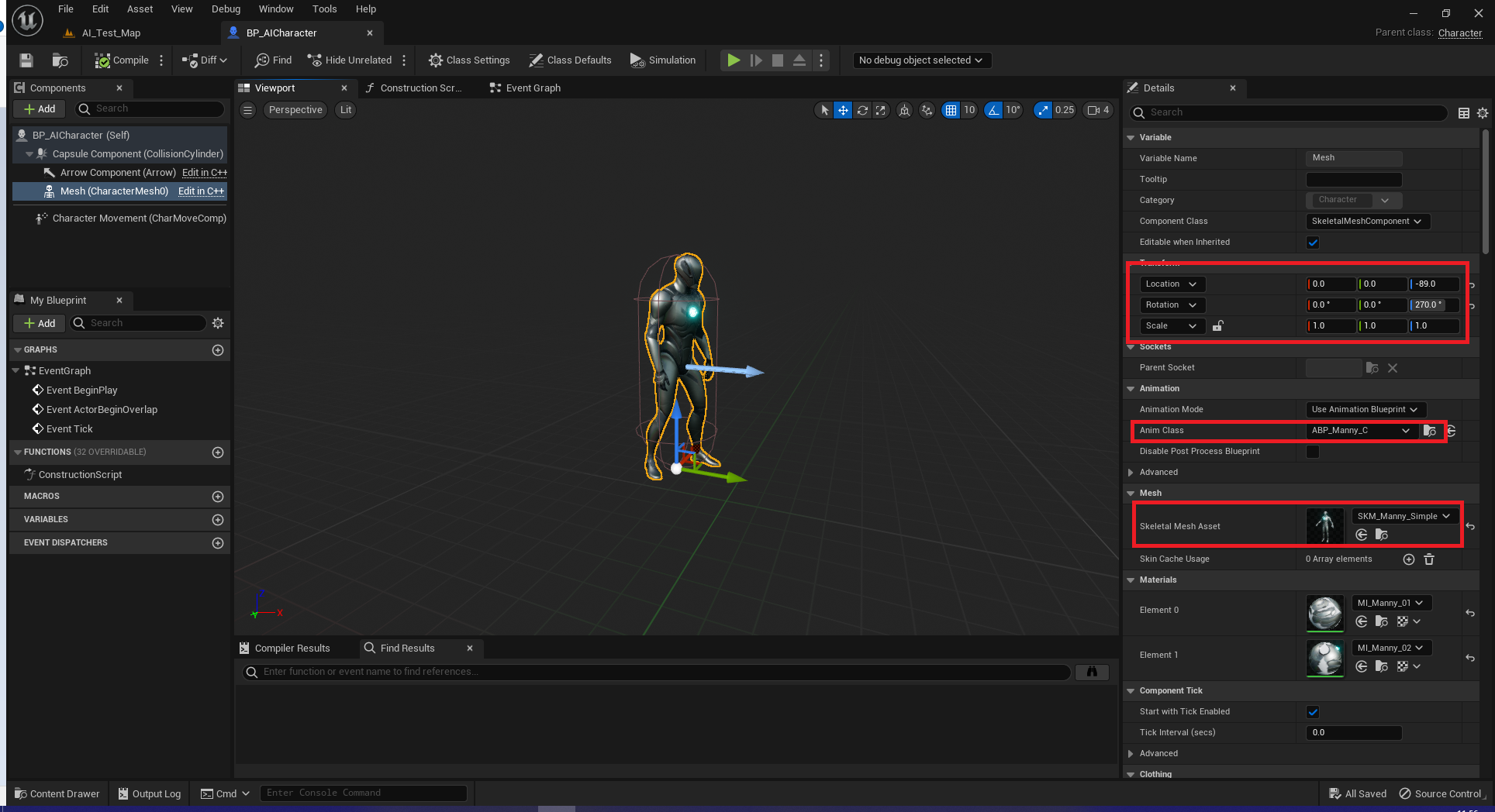
Next, create a new BP for a character. Apply a skeletal mesh and an animation blueprint. For testing, I have used the UE5 Manny and ABP_Manny_C, as detailed in the screenshot below:
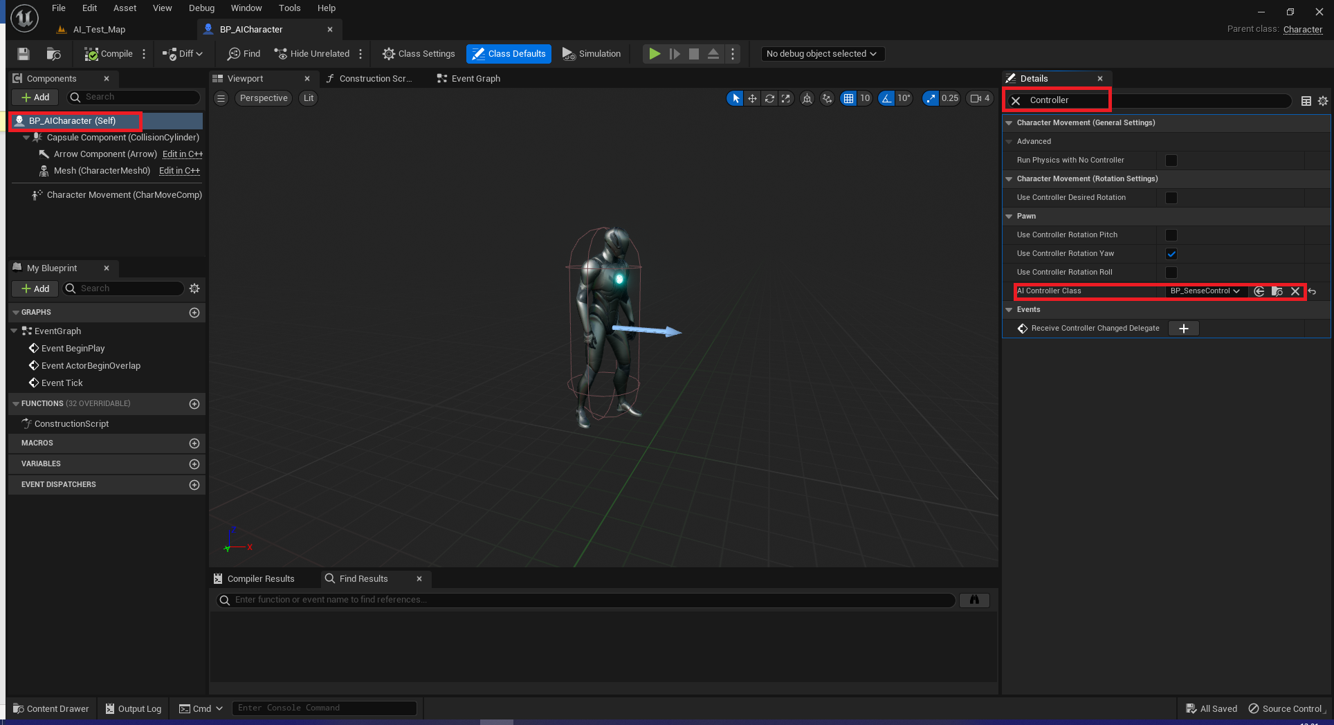
Next, we need to link our character to our controller. So, select the “(self)” in your character and search for controller. Under AI controller class select the controller you just made.
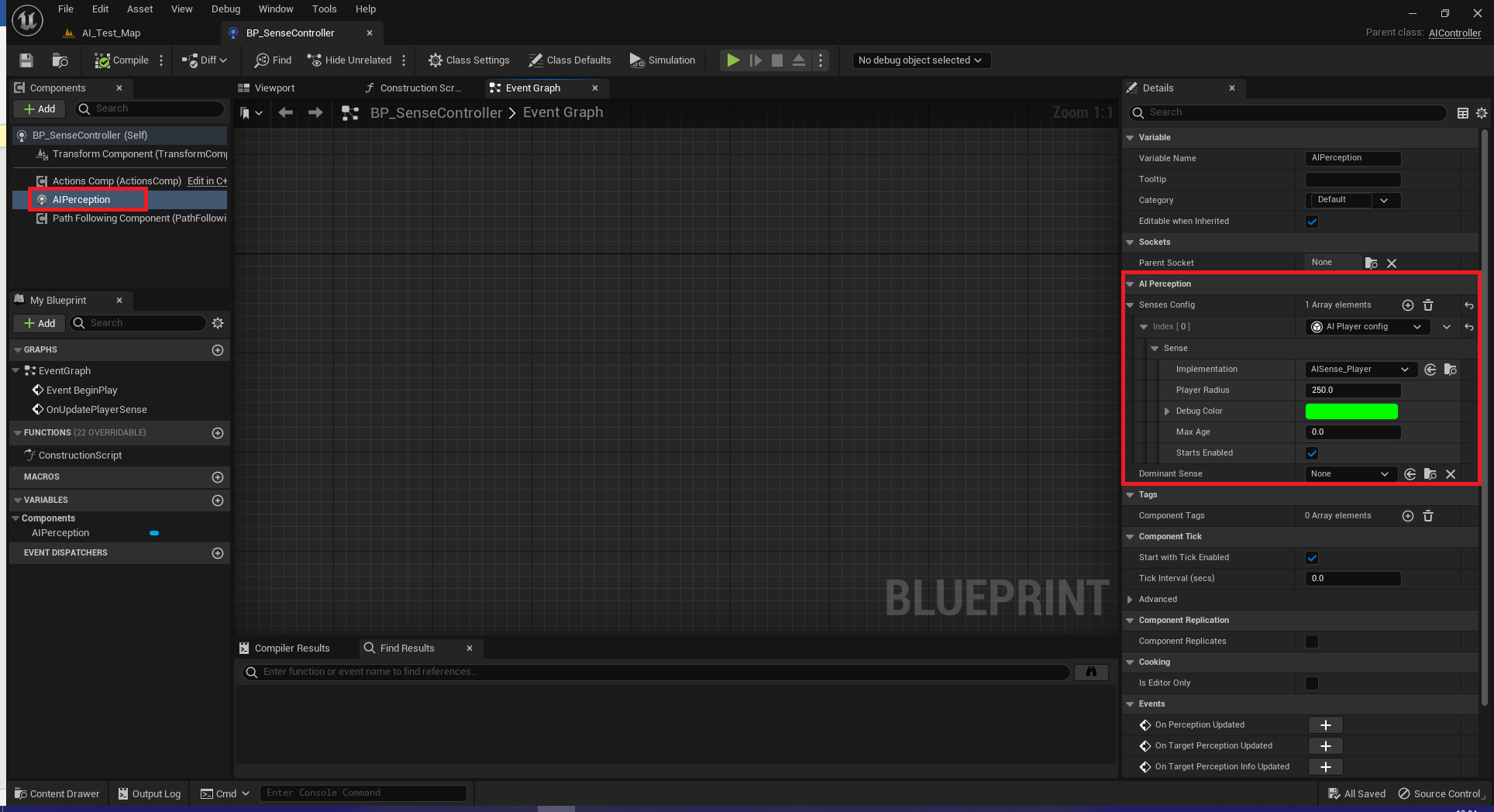
Now, let’s go to the controller. In the components tab of your controller add “AIPerception.” Select this new component, and on the right (in the default layout) add a new “Senses Config.” Make sure your implementation is set to the AISense_Player, change your player radius as you see fit (I set mine to 250, instead of using the default 10), change your debug color if you want.
Now, I am going to show you the testing setup I used to ensure it was working. I did this setup and then just placed the pawn on the map and moved my character near the pawn to ensure it was working. I will not explain this setup outside of the BeginPlay() and why/how to set up the custom function (as these parts will remain the same in the final version).
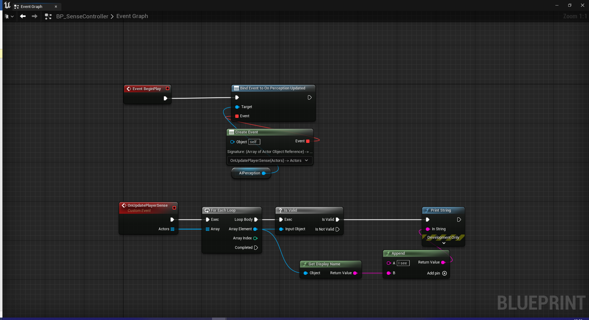
On BeginPlay we want to bind the AIPerception method OnPerceptionUpdated to a new custom function. This custom function will run our logic for what to do when the player is sensed. As we are looking at an array of actors in the C++ methods (look back at Update() as a reminder), this custom function needs to have an Array of Actors as an input parameter. (I also have a strong preference for using “Create Event” instead of linking the event pin to the event pin).
If you followed the above image, go ahead and test it. But now let’s move onto the vector math used to get the controlled pawn to flee the character. So, let’s create a new function (it will be a pure function) called GetFleeLocation and include an input of Actor and a return of Vector. This method will give us a new location (vector) for our controlled pawn to target.
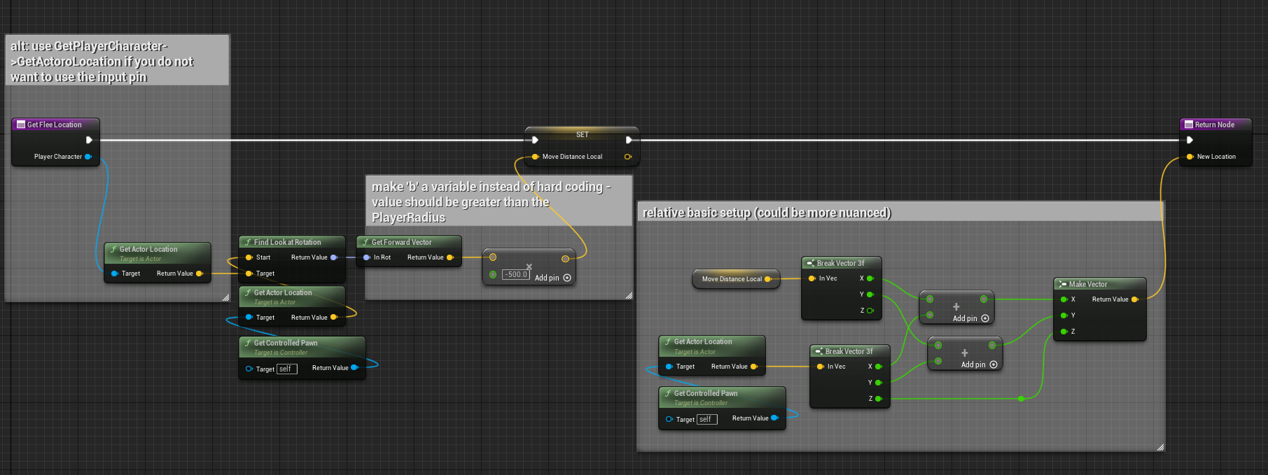
Some quick notes for this method:
- For some (“fun” reason) you cannot go from the Vector X Float node into the break vector in 5.1.
- You do not need to use an input node, you can use GetPlayerCharacter or GetPlayerPawn instead;
- The b value in the multiple need to be negative;
- The b value in the multiple should be a variable instead of hard coded;
- How you combine the current location and MoveDistanceLocal can be more nuanced (I just needed a quick example).
Now, we need to tell our pawn to go to this location. So, back on our event graph, we will use GetFleeLocation to store a vector for a new location. And, then, we will tell our AI to move there. It is a fairly simple setup:
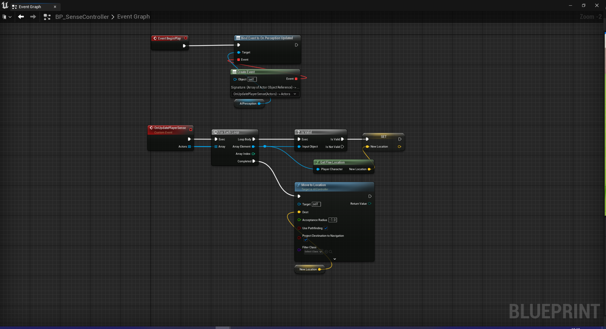
Some quick notes for the event graph:
- The AI will complete its move to before going to a new location;
- This means that if the player is pursuing, the pawn will come to a stop before continuing to flee;
- Before you ask, the above will pursuit even if you add it to loop body.
Step 5: NavMesh, Debugging AI, and testing
Okay, I could end the blog here and say we are done, but we did this nice little method with the gameplay debugger, so let’s look at that.
First, place your pawn in a level.
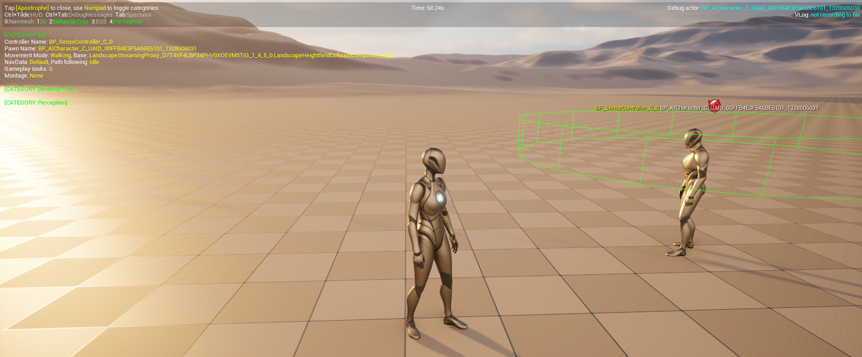
Second, make sure your map has a NavMeshBounds appropriately sized (remember ‘P’ is the hotkey to see the bounding area). It should look something like this – I’m using the default open world map in UE5, so ignore the map itself and focus on the pawn and the green:
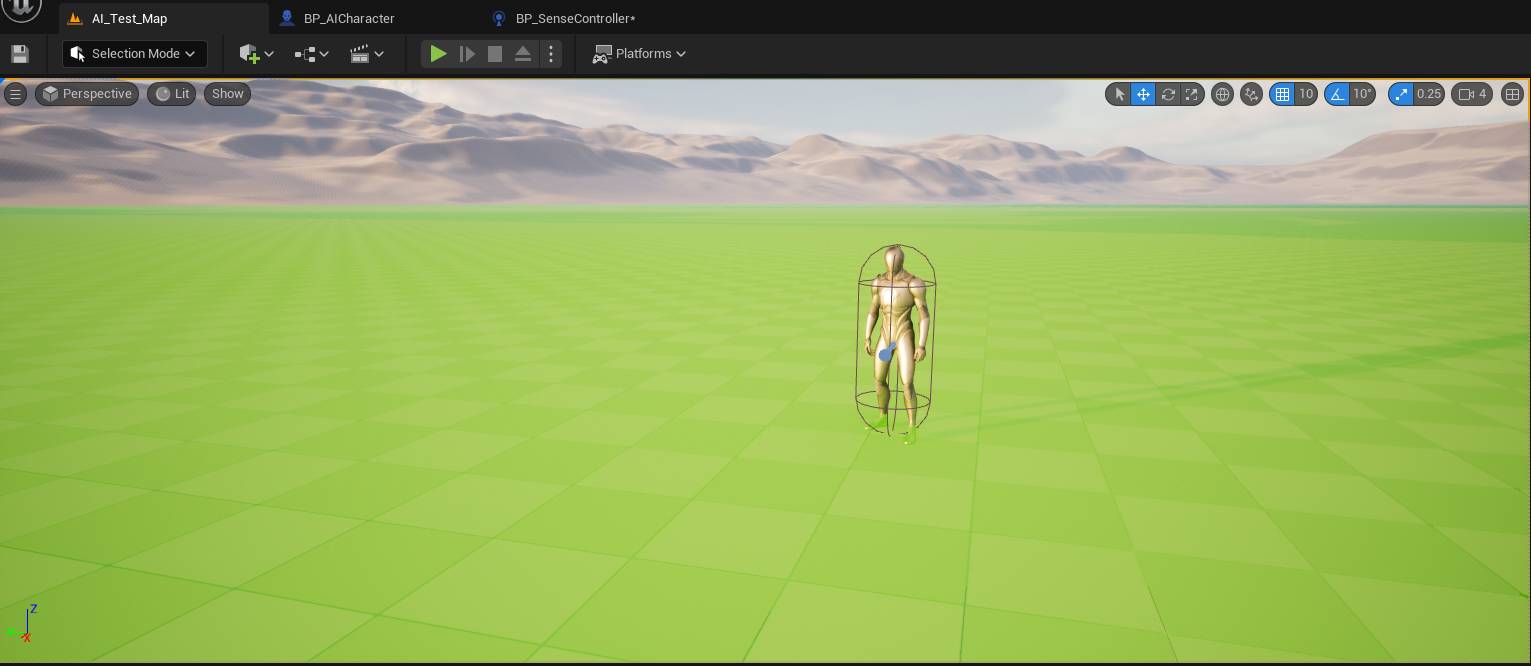
Go ahead and test it out.
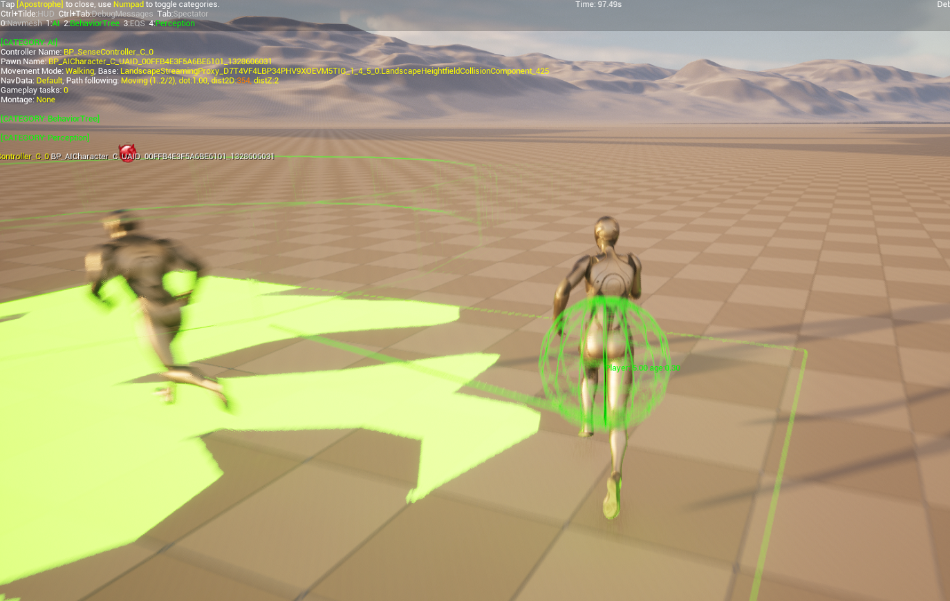
If you want to see the debugger in play:
- Hit the apostrophe key (‘) – this will bring up the AI debugger;
- Then hit ‘4’ on the numpad – this will bring up our collision area for our new sense.
Bibliography
To develop my own AI sense and to write this up, I used the following code as a guide:
- AISense_Sight.cpp
- AISense_Sight.h
- AISense.cpp
- AISense.h
- AISenseConfig.h
- AISenseConfig_Sight.h
- AISenseConfig_Damage.cpp
- AISenseConfig_Damage.h
Notes (for part 1):
First, one of my favorite things about Unreal being open source is finding notes, bugs, and other things in it. I enjoy this not because I want to laugh at the coding team at Epic. Rather, I enjoy it for the same reason I use to tell my students at university to find mistakes in published papers. It helps with the imposter syndrome and to develop confidence in whatever we are working on (be it code, research, or academic papers). It helps, at least for me, remind that we are all human and make mistakes.
Okay, why am I banging on about this? Well, there is one of these little comments in the code I used to help setup my own AI sense. In AISense_Sight.cpp on line 334 is this little gem: “// @todo figure out what should we do if not valid.”
Second, please bear in mind while I use a lot of Epic’s own architecture and design (though I did re-order some aspects), we did not use their query system (take a look at AISense_Sight.cpp lines 238 through 332).
PART 2
Okay, so like I hinted at the start, the approach we used in part 1 is pretty foolish. It is a waste of resources. Why? Well simply put we can use existing systems or less intensive systems to achieve the same results. Okay, then why did I make this system? I am an educator. I am hopefully giving you theory that you can use to build your own sense that has more utility and whose cost is actually justified.
What approaches would make more sense? First, we could just use the AISense_Sight system and if it sees the player it can flee. Now, if we are thinking about Scardys in PacMan, we might have a bVulnerable flag that needs to be set to true before the character flees (i.e., EQS sees player && bVulnerable is true, then flee). I think that system is fairly simple to setup, and also is not in the scope of what we are teaching, so I will not get into it. Second, a simpler system that is essentially the same as the first, and the system we created in part 1. Add a collision volume (I recommend a sphere) around the enemy pawn. If the OtherActor == GetPlayerCharacter(), then flee. Of course, this has its own overhead to it. And third, we can create a similar system to that (without the sphere) to detect if the player is near and run it on the AI tick, which is what I did in my PacMan clone.
In my PacMan clone, as part of the AI tick (remember Part 1 runs on a tick system too), a function (CheckShouldFlee() was called). Now, admittedly, having written this in a rush there were probably better ways to write this function. (Note this AIController) It is a fairly simple function but let’s take a look at it and go line by line through it:
void AEnemyControllerBase::CheckIfShoudFlee()
{
	if(bShouldFlee)
	{
		if(CheckIsNearPlayer())
		{
			if(!bIsFleeing)
			{
				bIsFleeing = true;
				MoveAwayFromPlayer();
			}
		}
	}
}
Line 1: this function returns nothing, so we do not have a return type. Though we could return a bool if it is fleeing or not (as an alternative approach).
Line 3: This check is to determine if the ghost is in a vulnerable state. When the ghost is in a vulnerable state bShouldFlee is set to true. At all other times, this value is set to false, with one exception. That single exception is a ghost personality that is called CowardGhost who wanders but is always set to flee (this is part of the reason why in my rush I decided to run the AI tick the way I did). If you do something similar, be mindful that when you reset from the vulnerable state not to reset any enemies that might flee on the sight of the player regardless.
So, if the ghost should flee, we check if the player is near the enemy pawn.
Line 5: This is a simple inline function that returns a bool. This method, gets the Vector_Distance (from the UKismetMathLibrary) between player character and controlled pawn. It evaluates if this distance is under a particular tolerance, if it is then it returns true (the controlled pawn should flee), otherwise it returns false. This approach creates a fair bit overhead, as we are calculating this every frame. So, it may be worth considering what I could have done instead to avoid calculating the distance between the pawn and player each frame (This is really the overhead all the approaches we have discussed today have in common).
So, if the player is near the pawn, we check if are already fleeing.
Line 7: We do not want to flee if we are already fleeing. Right, this one was a bit tricky and added in to resolve a bug. The AI path finding locked up in particular cases (for example, one such case was if the player was still, and the AI got near and then the player followed the enemy pawn). Or the AI would sometimes “flee” directly into the character (the above example also applies here). Neither were optimal. If the enemy pawn is already fleeing, it will not try to abort its current pathing. This eliminated the number of times the pawn just froze or ran directly into the character while fleeing (in both cases).
So, the pawn is not fleeing, so it needs to flee!
Line 9: Here we just set the bool so that we do not re-trigger the flee event. This gets to false on the override of OnMoveComplete().
Line 10: This is a simple one line method that calls up the inherited method MoveToLocation() – I did not override this method. For our target location, I have method (which should be inline) that uses some vector math to find a location in the opposite direction of the player. This vector math is the same as we used in our blueprint above (except it was in C++).
All-in-all, it is a fairly simple system. It lacks nuance (when the enemy is in a vulnerable state). But it got the job done.
Notes for Part 2:
So, I just want to address my use of brackets really quickly. I use brackets for one line if-statements for three reasons. Personally, I find it easier to read. I also find it easier to read when the starting bracket is on a new line. This just how my eyes process information (back in 2014 when I was taking my first course on Machine Learning for Data Scientists, while the instructor was brilliant, I struggled to read his code and only worked out a year after it was because of this). Second, I have had new programmers report that they find it easier. Third, and this is a big one for industry professionals, it adheres to Epic’s conventions.
Alright, that covers everything I wanted to address in this blog post. I hope to see you in the next blog post (or tutorial video). And, as always, I hope you have a wonderful day!










Recent Comments